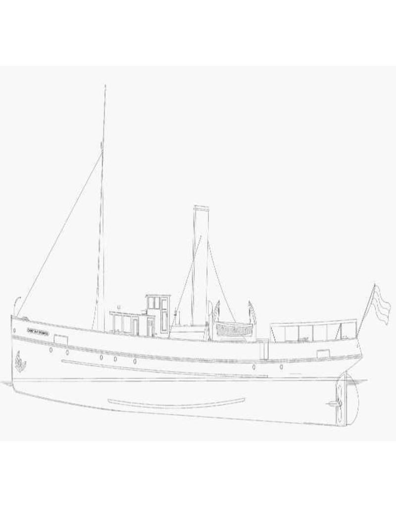
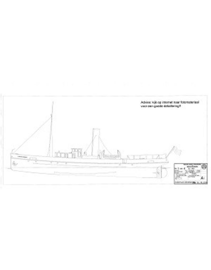
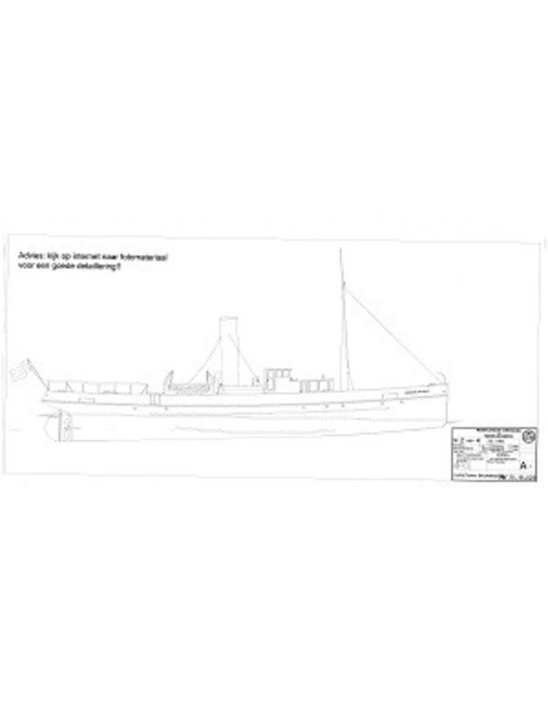

 - Construction Drawing Scale 1 : 50 (10.18.029)")
 - Construction Drawing Scale 1 : 50 (10.18.029)")
 - Construction Drawing Scale 1 : 50 (10.18.029)")
 - Construction Drawing Scale 1 : 50 (10.18.029)")
 - Construction Drawing Scale 1 : 50 (10.18.029)")
 - Construction Drawing Scale 1 : 50 (10.18.029)")
 - Construction Drawing Scale 1 : 50 (10.18.029)")
 - Construction Drawing Scale 1 : 50 (10.18.029)")
 - Construction Drawing Scale 1 : 50 (10.18.029)")
| Article number: | 10.18.029 |
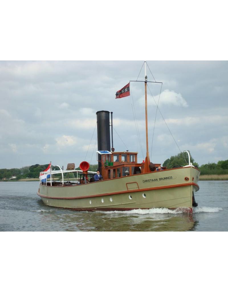
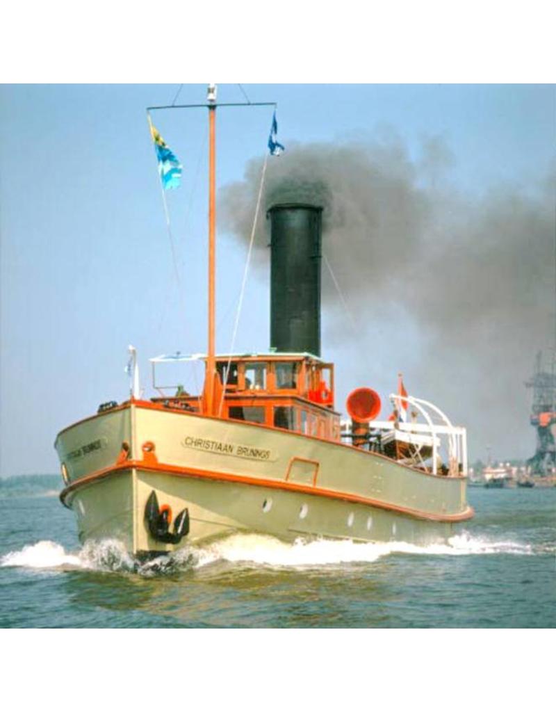
The ship was delivered in November 1900. The shipyard was De Nachtegaal on Bickerseiland (Western Islands, Amsterdam). The shipyard was owned by J.F. Meursing. The client for the construction of the SS Christiaan Brunings was RWS (Rijkswaterstaat) Dordrecht district.
Christiaan Brunings (1737–1805) worked and lived in Halfweg and is regarded as the founder of RWS
It is an icebreaker and/or management vessel, commissioned by Rijkswaterstaat (1899) and intended for the waterways around Dordrecht.
The ‘steam installation’ provides the propulsion. It is a screw-propelled vessel; the propeller shaft itself is driven by a steam engine, with the energy generated in the boiler. Such an installation alone weighs 60,000 kg, including water and coal, and takes up over 50% of the ship’s space. Although engines were already in use by 1900, they were not an option for the Christiaan Brunings. The propulsion system of an icebreaker/tug must be able to respond immediately to the demand for more power, something an engine was not yet capable of at that time.
The system consists mainly of three heat exchangers.
The boiler, an external heat exchanger. Here, the calories from the fuel – in our case, coal – are released and transferred to the water; 60% of the released calories are utilised, whilst 40% is lost through radiation and exhaust gases. (Modern coal has a gross calorific value of 6000 cal, so there is a loss of 2400 cal.) Of these calories, at least 90% is used to convert boiler water (100°C) into steam (100°C), whilst 10% is stored in the steam, causing an increase in the steam’s temperature and pressure.
The compound engine, a two-stage expansion engine, with two cylinders. Due to the pressure difference between the boiler and the engine, the steam flows from the boiler to the engine. In the engine, the calories (the 10%) stored in the steam are converted into power. (Calculate 10 kg of steam per IPK; 1 HP is 663 cal. Steam cools from 168 °C to 60 °C) Via the piston (rod) and connecting rod, the power is transmitted via the crankshaft to the propeller shaft.
The condenser, a surface condenser (originally also an ejection condenser), is directly coupled to the engine at the LD outlet; on the water-cooled surface, the steam condenses, causing a vacuum; the steam condenses at 0.25 atm at 60 °C; the wetter the steam leaving the LD cylinder (14%), the higher the efficiency. The steam is cooled back down to feedwater temperature and pumped back to the boiler.
The installation is designed for approximately 225 IPK (Indicated Horsepower); 225 IPK is the economic output, with an efficiency of 6 to 7%. This is achieved at 145 rpm, 18 to 20 km/h.
In the event of icebreaking, the installation can generate up to 260 IPK at 160 rpm. This is not economical, as the coal flies out of the chimney. The condenser cooling water will become very hot!
The boiler is a so-called ‘Scottish boiler’, developed in the second half of the 19th century; it is a large cylindrical shell made of SM steel, with riveted joints. A fire-tube boiler with returning gases means that the hot gases released in the firebox flow backwards, rise up into the firebox, and flow back to the front of the boiler through the fire tubes, leaving the boiler via the smoke box and chimney.
The steam engine is a compound engine; this is a machine in which the heat energy supplied by the steam is utilised across multiple cylinders. This is known as compounding. It can take place in 2, 3 or 4 stages, across 2 or more cylinders. The steam acts as a carrier of heat energy; compare it to petrol. By creating a vacuum, or negative pressure, the steam can release more heat energy and greater power can be generated. Compounding makes a greater temperature drop economically viable.
The compound engine on the Christiaan Brunings can be regarded as one of the last of its kind. The much more economical engine, the hot-head engine or pre-combustion engine, had been gaining ground since 1890, but was unsuitable for tugs; steam installations were equally unsuitable for small coastal/fishing vessels, as they left hardly any room for cargo. On tugs and passenger ships, the high-speed triples or horizontal engines supplanted the vertical compound engine. Its larger cousin, the long-stroke engine, began its rise in 1850; 1869 was a pivotal year, with Sulzer, for example, bringing standard engines to market in the 19th century and granting a licence to Werkspoor, amongst others (1892). The Triple Expansion Engine, or TEM, would dominate the cargo market right up until the Second World War (Liberty ships!).
The condenser is the third heat exchanger. The condenser currently in place is a so-called surface condenser, Hall 1832, which forms part of a closed circulation system: feed water, steam, condensate, feed water. Originally, an ejector condenser was also fitted; this is not part of a closed circulation system, as condensate is pumped overboard with cooling water, and the feed water is taken from the sea. With salty seawater, this is highly problematic; the boiler becomes salt-encrusted.
Specifications:
|
Drawing number |
10.18.029 |
|
Author |
L. Fontijn |
|
Description |
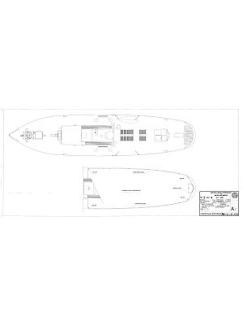
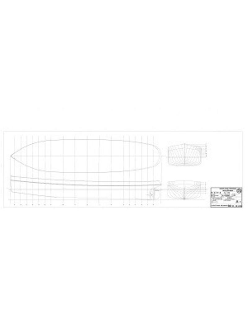
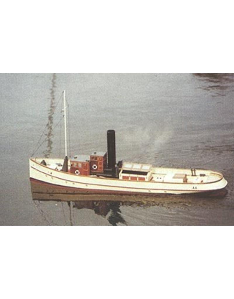
RWS Survey Vessel SS Christiaan Brunings (1900) |
|
Quality |
drawings; general plan; details |
|
Scale |
1 : 50 |
|
Number of A00 sheets |
0 |
|
Number of A0 sheets |
1 |
|
Number of A1 sheets |
3 |
|
Number of A2 sheets |
0 |
|
Number of A3 sheets |
0 |
|
Number of A4 sheets |
0 |
|
Total number of drawing sheets |
4 |
|
Number of A4 text sheets |
0 |
|
Weight in grams |
225 |
|
Details |
Overall length 82 cm |
|
Remarks |